Computer Networking for Developers: Networks and the Internet


We're using computer networks and the Internet all the time. Here at endjin, much of our work is done in Azure – a cloud platform that we communicate with over the internet and have some degree of control over the internal networking that our cloud-based applications depend on. The vast majority of the workings of networks are abstracted away from us, however considering we use them so much and are so dependent on them, especially as software engineers, it seems reasonable that we should have at least some understanding of how it all works.
The aim of this series of posts is to give an introduction to computer networks, the Internet and the Web, at a scope that is relevant to the software developer. Based on my brief foray into networking, it's obvious that it is a massive and complex subject, with many layers of details – many of which I will not cover (and do not understand) in order to keep things relevant.
This first post starts at the physical connections between computers, and gradually describes how to build increasingly larger networks; finishing with a discussion of the major protocols that enable information to be transported over the Internet.
Some background to computer networks
At one point in time all computers were working away on their own, oblivious to the existence of other computes. Over time, as interest in computing grew and more of them came about, people wanted to be able to share information between computers faster, and to be able to share resources across computers, for example having multiple computers share a single printer.
This is essentially what computer networking is: the study/topic of transferring information between computers.
Local Area Networks – LANs
The earliest networks could be found on small geographical scales, for example connections between devices in a single room or building – these are referred to as Local Area Networks (LANs).
Ethernet
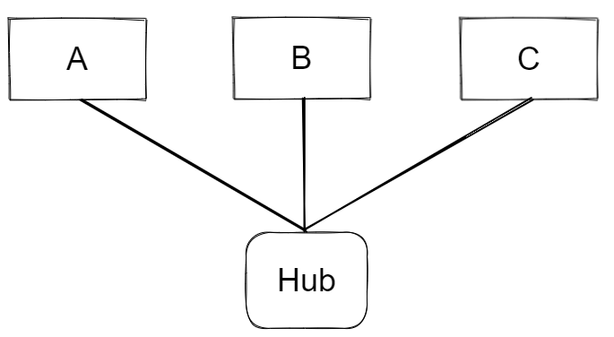
The most successful LAN technology is ethernet, developed in the 1970s and still in use today. You can think of an ethernet network as a group of computers connected together by cables. Each computer is connected by a cable to a device called an ethernet hub. When a device on the network wants to send a message – just a chunk of bits – to another device on the network, it writes the message to the ethernet cable. When the message reaches the hub it simply sends the message to every other device it is connected to – ethernet has a broadcasting behaviour: every other device that is on the network sees the message. The set of devices on an ethernet network are said to form a broadcast domain, since all devices are reachable via broadcast.
How does a given device know if a message is intended for it?
Every device has a unique Media Access Control – MAC – address, which is hard coded onto the device by the manufacturer. When the sending device wants the message to get to another specific device on the network, it prefixes the message with the binary representation of the intended device's MAC address – the address is said to be in the header of the message. So, every device on the network is listening for messages, when a message is sent over the cable every device sees the message and will read the MAC address from the header and compare with its own, if it matches – read the message, if not – discard the message.
What about Wi-Fi?
In basic terms Wi-Fi works the same way as ethernet, except that the bits being transmitted are encoded in radio waves travelling through the air, as opposed to in electrical signals travelling through copper wire in the case of ethernet. It has the same broadcasting behaviour as ethernet: when a message is sent, it is broadcast across the whole network with only the devices that the data was intended for reading the data, again using the MAC address mechanism.
Larger Networks
As more devices are added to the network the probability that two or more devices will try to write to the network simultaneously increases. This is known as a collision and causes the data to become scrambled. The set of devices whose messages can possibly collide with one another form a collision domain.
A solution to this problem is to split the LAN up into smaller networks, connected together with a switch device. Switch devices have a notion of memory: they know which devices are on each side of the network and so they can direct messages towards the intended device without needing to blindly broadcast the message across the whole LAN – reducing collisions and improving bandwidth.

Say if A is communicating with C, once the broadcasted message from A reaches the switch it will decide not to send it over to the ethernet segment containing devices D, E and F, since it knows the MAC address contained in the message header does not match that of any of the devices in that segment. This means that messages can be sent simultaneously across two ethernet segments, so long as the messages are intended for devices within the same segment, thus increasing network bandwidth.
Switches, therefore, reduce collision domains whilst maintaining the broadcast domain across the whole ethernet network, since the switch can decide if a given message will reach every device on the network or not, hence it's still a broadcast domain. In the network depicted in the figure above, devices A,B,C, and their hub form one collision domain; D,E,F, and their hub form another; devices A-F, the two hubs, and the switch form a broadcast domain.
Even Larger Networks
It is not possible to build Internet-scale networks using switch devices, there are upper limits on the number of switches that can be used in an ethernet network; switches essentially help build larger LANs. To go larger, we play the same game as before: split the network up into segments – each segment being a LAN - and connect the segments using a new device called a router. Routers are devices that know the addresses of other nearby routers and the addresses of the devices contained in LANs that they are connected to.

The network represented in the figure above is an internet (interconnected network) – notice I'm not saying the Internet (upper case I), which is the most famous example of an internet. This network could be considered to be a Wide Area Network – WAN.
The Internet Protocol (IP)
How do messages find themselves at the intended destination once they leave the starting LAN?
We know that LANs – using ethernet and Wi-Fi – don't much care about getting a given message to only the intended device - remember they have a broadcasting behaviour. But that's not how it works on the Internet. Messages carry with them an address that is unique to the device for which the message is intended. This address format is defined by the Internet Protocol (IP) and is called an IP address.
Every device connected to the internet gets an IP address. The actual address is four 8 bit numbers separated by dots. For example, here's the IP address of one of Google's servers:

The IP address is the addressing mechanism used by routers or, in other words, it is the addressing mechanism for messages once they're outside of a LAN (whereas the MAC address is the addressing mechanism when a message is inside a LAN). As with the MAC address, the binary representation of the IP address is prefixed to the data in the message as a header (note: for the purposes of keeping diagrams simple, I'm saying that the MAC address is included in the IP header).

Routers behave as follows: first check if the IP address contained in the message header matches that of one of the devices within a LAN that it is connected to, if not then it will forward the message on to another router (if the router can't figure out a suitable router to send to, it will drop the packet). The process repeats until the message arrives at a router that is connected to the LAN which contains the device with the same IP address as the one in the message header, then the message is sent onto that LAN, where it gets to the correct device using the MAC addressing mechanism.
To see an example of this, let's say device A in LAN1 wants to send a message to device K in LAN3. Device A adds the MAC address of its local router (since it knows the message needs to get outside of the LAN and the router is the device that can handle this), routerX, and the IP address of L to the message, and fires it off. When it reaches routerX, the router reads the MAC address, recognises that the message is intended for it and goes onto do its job: checks to see if the IP address is contained within the LAN that it is connected to (LAN2), which it isn't, and so it sends the message to routerY (routerX will also rip out its own MAC address from the header). RouterY then performs the same process; in this case routerY is connected to the LAN that contains the device with an IP address that matches the one in the message header (LAN3), and so the message is sent onto LAN3 where it reaches device K by the MAC address mechanism. (RouterY also handles figuring out what the destination device's MAC address is and adds it to the message, but we won't go into that).
Packet Switching
In practice whole messages are often too large to send over the internet. Say a large message is being transmitted between two routers somewhere on the Internet, that connection is being used up and no other message can get across it for a potentially long time – slowing the network down.
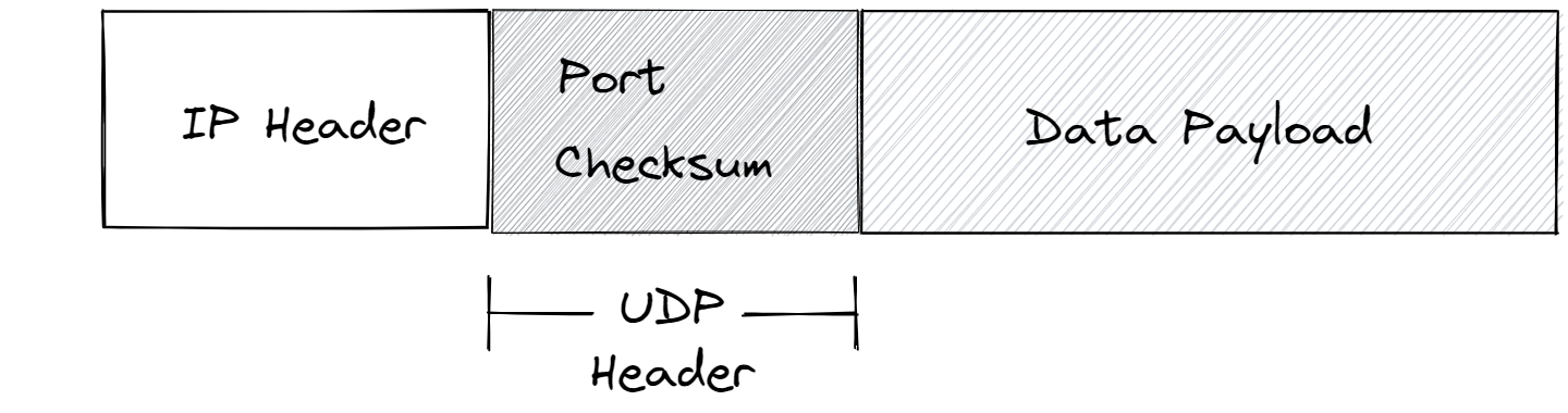
A solution to this is to break messages up into multiple packets – again you can just think of these packets as a collection of bits. The IP defines how messages should be split up and says that the packets must conform to its rules. As with whole messages, the IP address of the intended receiving device is bundled with the packet – the packets consist of an IP header and the data payload.

Improving Upon IP
IP is a low-level protocol, all's it has is the data payload and the IP address header. This isn't enough to do many of the things we regularly do on the internet. For example, when a computer receives a packet, how does it know which program the packet is intended for – Microsoft Teams or WhatsApp? Or, what happens when a packet doesn't arrive – can it be recovered?
For these reasons higher-level protocols were invented to sit on top of IP.
The User Datagram Protocol – UDP
UDP packets have their own header that sits inside the data payload of IP packets. This header contains a port number and checksum, these are the two main features that UDP adds to IP.
The checksum feature is to check for data corruption. When building the packets to be sent, the sending device performs a checksum algorithm on the data payloads of the packets and inserts the results into the UDP headers. When the packet arrives at the destination device it performs the same operation and compares it to the value in the header, if they match then all is good, if not - something has gone wrong during transmission and the packet will be discarded.
The port number is an addressing mechanism for indicating which program on the host machine the packet is intended for. Every program on a computer that wishes to connect to the internet will request a port number from its host OS. For example slack might be running on port 53442. When a packet arrives, the host OS will read the port number in the UDP header and pass the data payload to the program running on that port.
The Transmission Control Protocol – TCP
Notice that UDP has no mechanism for addressing missing data. Also, on large internets, like the Internet, there are multiple different paths a packet can take between any given start and end point. It is therefore possible for the packets related to a single message to arrive at the destination device at different times and out of order; UDP has no feature for addressing this issue either. This is where TCP comes in.
TCP introduces a number of features, the two major ones are acknowledgements and sequential ordering of packets.

When a device receives a TCP packet and it passes the checksum, it sends a packet back to the sending device as an acknowledgement that the packet has been received – called an ack. If the sending device does not receive an ack within some period of time, it will re-send the packet. This fixes the issues of lost or corrupted packages.
TCP packets are ordered sequentially, with the order value being stored in the TCP packet header. This way, if packets do arrive out of order, the receiving devices OS can re-arrange the packets into the correct order.
UDP Vs TCP
UDP has the potential to be faster as it's much simpler and doesn't send acks. Therefore UDP is used for time critical applications where speed is more important than data correctness, e.g. video streaming apps. TCP is more robust, and is therefore used when the data needs to arrive intact and in the correct order, e.g. when sending documents.
Why Protocols are Important
As you can imagine, the internet consists of many different types of devices with different and incompatible technologies. Every device on the Internet is – physically or other – connected to one another, and given that many of them are different and would like to communicate using their own rules, how is it that they can communicate with one another?
Protocols solve this problem, they offer a common language for devices to communicate with each other, without which the whole thing would be an incoherent mess. Every device that agrees to implement a protocol follows its rules, providing a consistent communication format for devices to send and receive packets.
The two essential features that IP provides are an addressing scheme, i.e. the IP address, and a delivery mechanism, i.e. IP packets - defining a standard way to group bits to be sent over the network as one. The way a device implements a protocol is by running a layer of protocol software; when a program wants to send data over the Internet, it will issue a system call to the OS, which will eventually pass an instruction to the protocol software (be it UDP, TCP, or other), which does the packaging up of the data into packets, appending address headers and so on.
So, what is the Internet?
It's an interconnected network, like I described earlier, with a collection of protocols that define a consistent communication format for devices to send and receive data to/from one another.
There's a hierarchy
One crucial aspect of the Internet, which I haven't mentioned, is that it is a hierarchical connection of networks covering different sized geographical regions.
One of the earlier diagrams depicted an internet formed of interconnected LANs, this could just have easily been an internet formed of interconnected WANs (just networks covering larger geographical regions), each of which could have contained multiple LANs interconnected themselves by other routers. You can go on like this up the geographical hierarchy to larger and larger interconnected WANs. You can build internets by using routers to interconnect whatever collection of LANs and different sized WANs you like.
To illustrate this, consider what might happen when your computer sends a packet to another computer far away, say, on another continent: the packet will start at your computer, reach your home router, then reach a router for your neighbourhood, then maybe one for your village, then maybe one for your city, and so on. Eventually it will start to come back down through smaller and smaller WANs around the geographical location of the destination computer until eventually getting onto its LAN.
The Domain Name System – DNS
We have established that to send a piece of data from one device to another over the internet you need the intended device's IP address.
So, how are we constantly communicating with devices over the internet without specifying an IP address
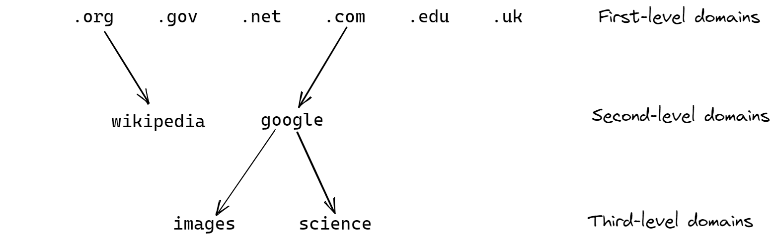
The answer is the Domain Name System (DNS), which is a huge database that maps domain names to IP addresses, this way people can remember the more human-friendly domain names rather than a bunch of numbers. A domain name is a set of words separated by periods, such as images.google.com.
If you type in the Google IP address mentioned earlier, followed by :80 – representing port 80, which is the standard port that servers run on – and hit enter, you will reach the Google search engine, the same page you could reach by going to www.google.com.
Tree structure of DNS
The set of domain names are structured in a tree-like hierarchy.
Conclusion
This post has started at the physical connection layer, where ethernet is king, going on to describe how bigger networks are constructed by interconnecting smaller networks with routers – internets! The major protocols, which establish a common language, enabling a diverse set of devices across the Internet to communicate, were also described.
If you could somehow magic-up all of this technology, you would have the ability to use your computer to send/receive data as packets of bits over the internet to/from other computers/devices. In order to perform the activities that we typically associate with the internet – visiting websites, streaming video, etc – you need more technology and protocols that sit on top of everything covered here, those will be discussed in part 2.